


Aerial Lift Joystick Malfunction: Common Causes & Step-by-Step Troubleshooting
Joystick Control System Failure: Fault Mechanism and Fleet Impact
In electric aerial work platform (AWP) rental and construction fleet operations, unplanned machine downtime is driven more frequently by electrical control system faults than by structural or hydraulic failures. JLG ES-series electric scissor lifts and electric boom lifts operate on a CAN bus (Controller Area Network) architecture in which the platform control module (PCM), ground control module (GCM), and drive/lift ECUs communicate via a differential two-wire network. The joystick assembly is not a simple on/off switch — it is an analogue signal transducer whose ratiometric output voltage is continuously sampled and validated by the ECU on every control cycle. Any disruption to supply voltage stability, harness line impedance, or CAN bus signal integrity will manifest first as a joystick control fault, even when the joystick assembly itself is electrically intact.
Fleet maintenance records consistently identify two upstream failure pathways. The first is harness or connector degradation introducing parasitic resistance into the joystick signal circuit, causing the ECU to read an out-of-range analogue voltage and log fault codes 144 (joystick out of range — platform control), 145 (joystick out of range — ground control), or 168 (joystick fault — drive circuit). The second is traction battery pack terminal voltage sag under peak dynamic load: when pack voltage drops below the ECU's minimum operating threshold during simultaneous lift-and-drive demand cycles, the control system initiates a low-voltage protective shutdown of all proportional outputs, disabling joystick response and generating a CAN bus signal loss event at the GCM. Both failure modes are fully confirmed and reproducible across JLG, Genie, Skyjack, and Haulotte electric scissor lifts and telescopic boom lifts, and represent universal electrical fault patterns applicable to all mainstream electric AWP platforms operating in North American and global rental and construction fleets.
The operational consequence in both cases is identical: a machine removed from active service, an unscheduled field service dispatch, and a lost production shift that correct component specification practice would have prevented.
Core Technical Parameters for Battery and Control Component Selection
Correct component specification is the primary engineering countermeasure against joystick-related control system faults. The selection criteria below apply exclusively to JLG ES-series electric aerial lifts for traction battery matching and OEM part number selection; the circuit detection methodology, CAN bus fault diagnosis procedures, multimeter voltage test protocols, and voltage drop failure logic described throughout this article are universally applicable across JLG, Genie, Skyjack, and Haulotte electric scissor lifts and telescopic boom lifts operating in any market.

Traction Battery Specification: Terminal Voltage, C-Rate, and Deep Cycle Performance
The traction battery pack is the primary DC power supply rail for the entire AWP electrical system. Under peak dynamic load — simultaneous drive motor current draw and lift solenoid actuation — the instantaneous current demand on a 24V system typically reaches 150–200A. At this discharge rate, a battery with insufficient deep-cycle capacity or elevated internal resistance will exhibit terminal voltage sag: a transient drop in output voltage that, if it falls below the ECU's low-voltage protection threshold (typically 18V on a nominal 24V system), triggers a full control system reset and logs a CAN bus signal loss event. This is the precise electrotechnical mechanism by which a degraded traction battery directly causes joystick fault codes without any defect present in the joystick transducer assembly itself.
The DC400-6 AGM (Absorbent Glass Mat) valve-regulated lead-acid battery is engineered for electric AWP traction applications with the following confirmed specifications:
- Nominal Voltage: 6V per cell block; series-configured banks deliver the 24V or 48V traction bus voltage required by JLG ES-series drive and lift ECU systems
- Rated Capacity: 400 Ah at C20 discharge rate; at the C5 discharge rate characteristic of AWP duty cycles, effective capacity is approximately 340–360 Ah — sized to sustain a full operational shift without mid-shift terminal voltage depression
- Cycle Life: 600–800 full discharge cycles to 80% depth of discharge (DoD) under IEC 60896-21 test conditions — approximately 2.5–3× the service life of standard mobility-class AGM cells operating at equivalent DoD
- Internal Construction: Absorbed glass mat separator technology eliminates free electrolyte stratification, suppresses active material shedding under vibration, and maintains consistent plate-to-separator contact pressure throughout service life — directly supporting stable terminal voltage under high C-rate discharge events
- Enclosure: Sealed VRLA construction; compliant with DOT 49 CFR hazardous materials transport regulations (North America) and IEC 60068-2 environmental test standards for on-machine battery installations in both indoor and outdoor job site environments
- Vibration Resistance: Recombinant gas design and compression-fit plate assembly qualified to IEC 60068-2-64 random vibration profile, appropriate for AWP traction battery service on uneven construction site and warehouse floor surfaces
DC400-6 Bank Configuration by JLG ES-Series Model — Exclusive Reference: JLG ES-Series Electric Aerial Lifts
Traction bus voltage and battery bank configuration are defined by the drive inverter and lift controller input voltage specification documented in the JLG model-specific service manual. The OEM part number and bank configuration must be verified against the machine serial number plate prior to any replacement. Mixed-chemistry or mixed-age cells within a series bank generate inter-cell voltage differentials that the Battery Management System (BMS) — where installed — will flag as an imbalance fault, and which on non-BMS machines manifest as unexplained joystick control faults caused by transient DC bus voltage collapse.
| JLG Model | Platform Type | Traction Bus Voltage | DC400-6 Bank Configuration |
|---|---|---|---|
| JLG 1930ES / 2030ES / 2630ES | Electric Scissor Lift | 24V DC | 4 × DC400-6 in series |
| JLG 3246ES / 4046ES | Electric Scissor Lift | 24V DC | 4 × DC400-6 in series |
| JLG 450AJ / 460SJ | Electric Boom Lift | 48V DC | 8 × DC400-6 in series |
| JLG 600S / 660SJ | Electric Boom Lift | 48V DC | 8 × DC400-6 in series |
Always cross-reference traction bus voltage against the machine data plate and the applicable JLG service manual before commissioning a replacement battery bank. Inter-cell capacity imbalance in an incorrectly configured series string is a confirmed root cause of recurring fault codes 144, 145, and 168: the ECU interprets the resulting analogue voltage offset as a joystick signal out-of-calibration-range event rather than a battery system fault, leading to repeated misdiagnosis and unnecessary joystick replacement.
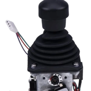
Joystick Assembly and Ground Control Module — Technical Selection Criteria
When replacing the joystick potentiometer assembly, ground control module harness, or PCM connector block, the replacement component must be matched to the exact JLG service manual part number revision applicable to the machine's serial number range. Technical parameters requiring verification prior to installation include: output signal voltage range (typically 0.5V–4.5V ratiometric on a 5V reference supply), connector housing type and pin count per the Deutsch DT or AMP Superseal series specified in the machine wiring diagram, operating input voltage range (9–30V DC for most JLG ES-series controllers), and ingress protection rating — minimum IP54 per IEC 60529 for standard outdoor job site environments; IP65 specified for wash-down, high-humidity, or coastal operating conditions.
Harness line impedance must be verified by point-to-point resistance measurement from the joystick connector to the PCM input pin before condemning the joystick transducer. A line resistance exceeding 2Ω on any signal conductor will produce a voltage drop sufficient to shift the joystick's ratiometric output reading outside the ECU's valid calibration window, generating fault code 144 or 145 without any defect in the joystick assembly itself. CAN bus signal attenuation caused by harness damage or incorrect termination resistance must similarly be ruled out before replacing CAN-connected control modules: CAN bus high/low differential voltage should measure 2.5V ± 1V at rest and 1.5–3.5V during active transmission; deviation outside this range indicates network wiring or termination resistance faults, not controller failure.

Three Procurement Errors That Generate Avoidable Maintenance Costs Across Global AWP Rental Fleets
Despite growing adoption of whole-life cost analysis in AWP fleet management, three procurement errors continue to generate disproportionate field service expenditure in both North American and international rental and construction fleet operations.
Error 1: Selecting Traction Batteries Without Verifying Deep-Cycle C-Rate Specification
Valve-regulated AGM batteries manufactured for standby UPS or light mobility applications are routinely misapplied to AWP traction duty because nominal voltage and physical case dimensions appear compatible. The technically critical distinction is discharge C-rate rating. UPS and mobility-class AGM cells are designed for float charge maintenance and shallow discharge at C10–C20 rates with a maximum DoD of 20–30%. AWP traction duty cycles impose continuous high-rate discharge at C4–C6 with routine DoD of 70–80% per operational shift. Applying a shallow-cycle cell to this load regime causes accelerated active material shedding, positive grid corrosion, and irreversible capacity fade, typically reducing usable service life to 150–250 cycles. In the control system, the consequence is progressive terminal voltage sag under load, generating intermittent fault codes 144, 145, and 168 that present as joystick or harness failures and consume substantial field service labor on repeated incorrect diagnoses before the battery pack is correctly identified as the root cause.
Error 2: Installing Non-OEM Control Components Without EMC and Firmware Validation
Uncertified aftermarket joystick assemblies and control harnesses sourced from unvalidated third-party distributors frequently fail to satisfy the electromagnetic compatibility requirements specified under ANSI/UL 583 (electric industrial trucks — applicable by reference to AWP control systems) and internationally under ISO 14982 (agricultural and forestry machinery EMC, cross-referenced in AWP standards). Beyond compliance risk, the technical failure mode is specific and reproducible: aftermarket joystick potentiometers with resistance tolerance deviations outside the OEM specification (typically ±1%) produce a resting output voltage that the ECU registers as a pre-fault offset condition, logging a persistent fault code 168 that cannot be cleared by the standard JLG DaVinci controller calibration routine. In CAN bus-equipped models, a non-OEM GCM or PCM with incorrect CAN bus termination resistance — the network specification requires a precise 120Ω termination impedance at each physical bus endpoint — introduces signal reflections that corrupt the differential voltage waveform, producing sporadic multi-system fault events across the entire control network. This failure mode generates diagnostically ambiguous fault logs that substantially increase diagnostic labor time and total repair cost.
Error 3: Commissioning Mixed-Age Battery Banks During Partial Cell Replacement
Partial battery bank renewal — substituting one or two degraded cells into an existing series string to defer full replacement cost — is the most frequently documented source of recurring voltage-related joystick faults in fleet-scale AWP maintenance operations. Within a series-connected battery bank, the cell with the lowest available capacity governs the effective output voltage and current delivery of the entire string under high-rate discharge. New cells inserted into an aged string are forced to sustain a disproportionate share of the discharge current, accelerating their own capacity loss through thermal cycling and plate sulfation. The inter-cell voltage differential that develops — measurable as a delta exceeding 0.3V per cell at open-circuit rest — creates a dynamic DC bus voltage instability that the AWP ECU interprets as an anomalous joystick signal offset, logging control faults and in certain fault conditions triggering the overvoltage protection relay, which immediately removes all machine functions from service.

Technical Procurement Recommendations for AWP Fleet Maintenance Operations
For fleet operations managing five or more electric AWP units, component specification discipline directly determines field service dispatch frequency and total maintenance cost per machine per year. The maintenance economics are unambiguous: a single unscheduled field service call to diagnose and correct a battery-induced joystick fault — including technician travel time, on-site diagnostic labor, and machine out-of-service standby — represents a total maintenance cost that substantially exceeds the specification premium of an OEM-grade deep-cycle traction battery.
We recommend provisioning the DC400-6 AGM battery as the standard traction battery replacement unit across JLG ES-series electric scissor lift and boom lift inventory. Its 400 Ah rated capacity, 600–800 cycle deep-discharge service life, IEC 60068-2-64 vibration qualification, and sealed VRLA construction satisfy the OEM electrical and mechanical interface requirements for the duty cycles characteristic of North American and global rental and construction fleet operations — commercial construction sites, industrial maintenance facilities, infrastructure projects, and warehouse distribution operations.
For joystick potentiometer assemblies, ground control modules, PCM connector harnesses, and CAN bus termination components, we supply a complete range of certified JLG ES-series compatible spare parts validated against the applicable service manual part number revisions and compliant with relevant AWP electrical safety and EMC standards. [→ Browse our JLG Spare Parts catalogue] [→ View DC400-6 AGM Battery product page]
Volume procurement contracts are available for rental and construction fleet operators, with distribution logistics coordinated to support both North American and international fleet maintenance operations.
Conclusion: Fault Prevention Begins at Component Specification
JLG AWP joystick control faults are, across the dominant failure mode distribution, not primary joystick transducer failures. They are secondary electrical manifestations of either traction battery terminal voltage sag under high C-rate discharge load, or control harness parasitic impedance and CAN bus signal attenuation caused by non-compliant aftermarket components or connector degradation. Fault codes 144, 145, and 168 logged by the JLG ECU indicate that the analogue joystick signal voltage has exceeded the valid ratiometric calibration window — but the root cause resides upstream in the DC power supply rail or signal transmission circuit, not necessarily in the joystick transducer assembly itself. Fleet maintenance supervisors and technical procurement managers who enforce correct deep-cycle battery C-rate specification, whole-bank replacement discipline, and OEM-validated control component sourcing will achieve measurable reductions in control system fault frequency, unscheduled field service deployment, and lost machine utilization across their AWP fleet inventory.
The three operative technical controls are: verify battery bank configuration against machine traction bus voltage and replace the complete series string as a matched set; enforce OEM or OEM-validated part number traceability for all joystick potentiometer, harness, and GCM replacements; and specify traction batteries by AWP duty-cycle C-rate rating and DoD capacity, not by nominal voltage and case geometry alone.
For fleet-level technical procurement consultation, volume order quotations, or fault diagnosis support on specific JLG ES-series models, contact our technical after-sales team directly. We provide component specification and compatibility support to fleet maintenance supervisors, field service technicians, and procurement managers supporting AWP operations worldwide.


